This program uses the RoboArm T-54 from the Robo Center challenges in the LEGO NXT-G programming environment. It has been inspired by the programming examples for the RoboArm T-54, and is a natural extension of the programming examples given. The program removes the red ball from a pedestal and moves the blue ball from one pedestal to the other. It does not matter which order the balls are in. If the blue ball is on the right pedestal, then the program removes the red ball from the left pedestal, and moves the blue ball to the left pedestal. If the blue ball is on the left pedestal, then the program removes the red ball from the right pedestal, and moves the blue ball to the right pedestal.
The program makes use of a state variable to determine which action the RoboArm robot will take next. When designing the code for a state machine a good idea is to first make a table of all the states the robot may have. The table should list all the states, the condition of the robot in each state, the actions which will be performed in that state, and what the next state(s) will be. Since the T-54 has sensors, the inputs from the sensors, along with the robot state, determine the next state. The table below provides an example of a state table for a robot. The first column is a numerical identifier which the software can use to identify states. The second column lists the condition of the robot in that state. The third column lists the actions that will be taken while in that state, and the last column lists the next state(s) that the robot can take. The next state(s) are usually a function of inputs, such as from the NXT sensors.
For the T-54 the conditions are determined by the horizontal position of the arm, the vertical position of the arm, and whether the hand is open or closed. The horizontal position of the arm is either over the left pedestal or over the right pedestal. The vertical position of the arm is either raised or lowered. The hand is either: 1) opened, 2) closed and holding nothing, or 3) closed and holding an object. The next state column lists the numerical ID of the next state and the condition of the inputs determining that state (if any).
| State | State Conditions | Next Action(s) | Next State |
|---|---|---|---|
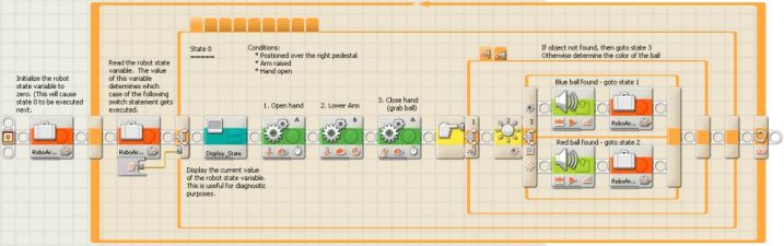
| 0 |
• Right pedestal • Arm up • Hand open |
1. Open hand 2. Lower arm 3. Close hand - grab ball |
1, if have blue ball 2, if have red ball 3, if have no object |
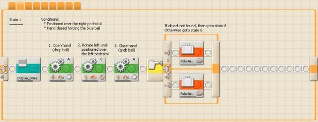
| 1 |
• Right pedestal • Hand closed • Holding blue ball |
1. Open hand - drop ball 2. Rotate to left pedestal 3. Close hand - grab ball |
6, if have ball 8, if no object |
| 2 |
• Right pedestal • Hand closed • Holding red ball |
1. Rotate half way to left pedestal 2. Open hand - drop ball 3. Continue rotate to left pedestal 4. Close hand - grab ball |
5, if have ball 8, if no object |
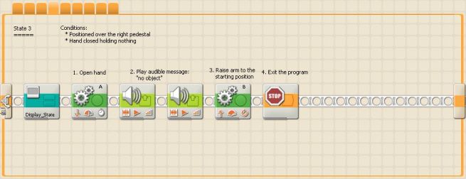
| 3 |
• Right pedestal • No object • Hand closed |
1. Open hand - drop ball 2. Sound alarm 3. Raise arm 4. Exit program |
NXT OS Shell |
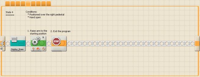
| 4 |
• Right pedestal • No object • Hand open |
1. Raise arm 2. Exit program |
NXT OS Shell |
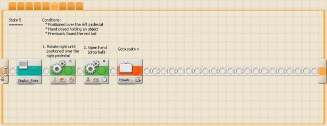
| 5 |
• Left pedestal • Hand closed • Holding ball • Previous ball red |
1. Rotate to right pedestal 2. Open hand - drop ball |
4 |
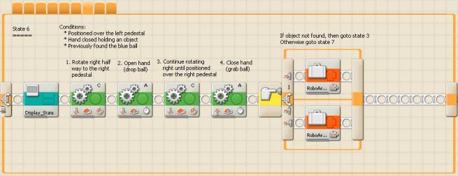
| 6 |
• Left pedestal • Hand closed • Holding ball • Previous ball blue |
1. Rotate half way to right pedestal 2. Open hand - drop ball 3. Continue rotate to right pedestal 4. Close hand - grab ball |
7, if holding ball 3, if no object |
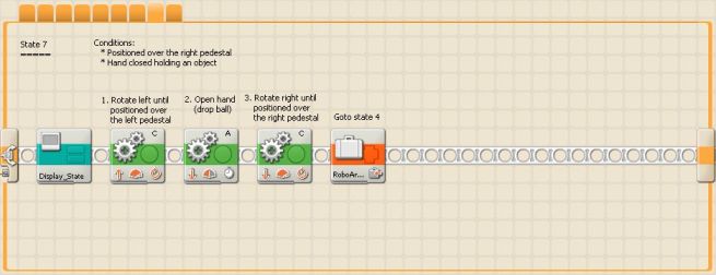
| 7 |
• Right pedestal • Hand closed • Holding ball |
1. Rotate to left pedestal 2. Open hand - drop ball 3. Rotate to right pedestal |
4 |
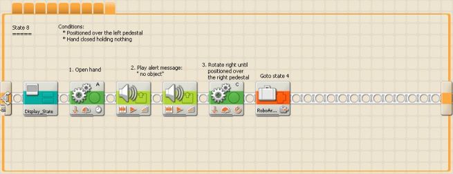
| 8 |
• Left pedestal • No object • Hand closed |
1. Open hand 2. Sound alarm 3. Rotate to right pedestal |
4 |
The program uses a state variable "RoboArm_State" to keep track of the state of the T-54. When the program first starts RoboArm_State gets initialized to 0, so that case 0 of the switch statement gets executed first. Depending on the outcome of state 0, RoboArm_State gets set to 1, 2, or 3. The value of RoboArm_State will be the next case of the switch statement to be executed. Each state (except the states that end the program) sets RoboArm_State to the next case of the switch statement to be executed. This illustrates how the NXT-G switch statement can be used to implement a state machine. Additionally a MyBlock is used to display the state that is currently executing on the NXT. Displaying the current state is useful for debugging and diagnostic purposes. This MyBlock "Display_State" merely reads the value of RoboArm_State and displays it on the LCD display of the NXT.
One of the cool things about state machines is how they naturally handle exceptional conditions. For example, suppose there is a blue ball on the right pedestal, but the left pedestal has nothing on it. Then state 8 will be executed followed by state 4, which will return the T-54 to its initial state and exit the program. If you download and run this program, you should try all possible combinations: right pedestal empty, left pedestal empty, blue ball on right pedestal and red on left, red ball on right pedestal and blue on right, and etc. One of the challenges of testing software utilizing state machines is to test every possible state and state transition. This can be quite a daunting task for real life programs. However, for systems like the NXT, a state machine very often results in optimal code size-wise and speed-wise. You can download the source code for this program by clicking on the link at the bottom of this page.
Tip: Use weights to hold down the pedestals for the red and blue balls. Using weights will prevent the pedestals from tipping over when the hand picks up or drops a ball on them. Personally, I find that one inch, round fishing weights work quite well.